Color System
What is a Color System?
A color system is a way of representing colors in an image. There are two types of color systems: additive and subtractive. Additive color systems are used for displaying colors on a screen, while subtractive color systems are used for printing colors on paper. The most common color systems are RGB, CMYK, and HSV.
The properties that distinguish different color usually brightness, hue, and saturation. Brightness is the amount of light reflected by the color, hue is the color of the light reflected, and saturation is the purity of the color. The more white light is added to a color, the less saturated the color is.
Categories of Color Systems
Digital Color Systems
YIQ
The YIQ color system is used in NTSC television broadcasting. In YIQ, \(Y\) component represents the luma information, and is the only component used by black-and-white television receivers. \(I\) and \(Q\) components represent the chrominance information, \(I\) stands for in-phase, and \(Q\) stands for quadrature.
To convert from RGB to YIQ, the following formula is used:
\[\begin{bmatrix} Y\\ I\\ Q \end{bmatrix} = \begin{bmatrix} 0.299 & 0.587 & 0.114\\ 0.596 & -0.274 & -0.322\\ 0.211 & -0.523 & 0.312 \end{bmatrix} \begin{bmatrix} R\\ G\\ B \end{bmatrix}\]To convert from YIQ to RGB, the following formula is used:
\[\begin{bmatrix} R\\ G\\ B \end{bmatrix} = \begin{bmatrix} 1 & 0.956 & 0.621\\ 1 & -0.272 & -0.647\\ 1 & -1.106 & 1.703 \end{bmatrix} \begin{bmatrix} Y\\ I\\ Q \end{bmatrix}\]YCbCr
YCbCr color spaces are defined by a mathematical coordinate transformation from an associated RGB primaries and white point. Y stands for luma, Cb stands for blue-difference chroma, and Cr stands for red-difference chroma. To convert from RGB to YCbCr, the following formula is used:
\[\begin{bmatrix} Y\\ Cb\\ Cr \end{bmatrix} = \begin{bmatrix} 16\\ 128\\ 128 \end{bmatrix} + \begin{bmatrix} 65.481 & 128.553 & 24.966\\ -37.797 & -74.203 & 112\\ 112 & -93.786 & -18.214 \end{bmatrix} \begin{bmatrix} R\\ G\\ B \end{bmatrix} /256(about)\]Additive Color Systems
RGB
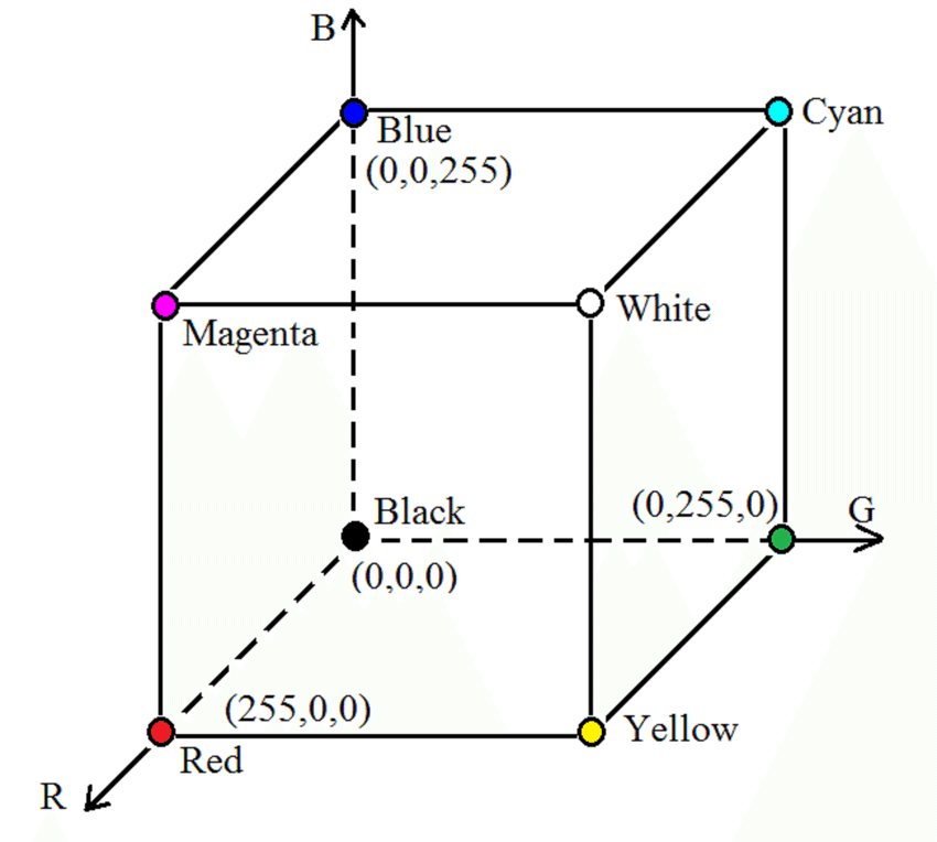
In RGB color system, each color is represented by a combination of red, green, and blue. The value of each color ranges from 0 to 255. For example, the color red is represented by (255, 0, 0), while the color white is represented by (255, 255, 255), and the color black is represented by (0, 0, 0).
Below is cubical representation of the RGB color system, where each axis represents a color (red, green, and blue). The color white is at the center of the cube, while the color black is at the origin of the cube, and the color white is at the opposite corner of the cube. The other three corners of the cube represent the secondary colors: cyan, magenta, and yellow.

Subtractive Color Systems
CMY
As mentioned above, cyan, magenta, and yellow are the secondary colors in the RGB color system, standing for C, M, and Y in the CMY color system. The CMY color system is a subtractive color system, which means that the more colors are added, the darker the color becomes, as C, M, and Y can be calculated as follows:
\[\begin{bmatrix} C\\ M\\ Y \end{bmatrix} = \begin{bmatrix} 1\\ 1\\ 1 \end{bmatrix} - \begin{bmatrix} R\\ G\\ B \end{bmatrix}\]where all the values are in the range of 0 to 1 (\(p/255\)).
It is worth noting that the surface of pure cyan/magenta/yellow does not reflect red/green/blue light.
CMYK
In practice, C, M and Y inks are usually not pure, and the color black is usually added to the ink to make the color darker. The CMYK color system is a subtractive color system that uses cyan, magenta, yellow, and black to represent colors. To convert from CMY to CMYK, the following formula is used:
- Let \(K\) be the minimum of \(C\), \(M\), and \(Y\), \(K = min(C, M, Y)\).
- If \(K = 1\), then \(C = M = Y = 0\). Otherwise,
To convert from CMYK to CMY, the following formula is used:
\[\begin{aligned} C &= C \times (1 - K) + K\\ M &= M \times (1 - K) + K\\ Y &= Y \times (1 - K) + K \end{aligned}\]Note that all the values above are in the range \([0, 1]\).
Other Color Systems
The disadvantage of the RGB color system and the CMY(K) color system is that they are not easy to understand for humans. Usually, humans describe colors using hue, saturation, and brightness. Hue is the category of the color, saturation is the purity of the color, and brightness is the amount of light reflected by the color. Accordingly, there are several color systems that are designed to be more intuitive for humans, such as HSL, HSV, and HSI.
HSI
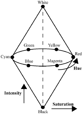
The HSI color model represents every color with three components: hue (H), saturation (S), and intensity (I). The hue component is a value between 0 and 360, 0 being red, 120 being green, and 240 being blue.
\[H = \left\{ \begin{aligned} \theta &\text{ if } B \le G\\ 360 - \theta &\text{ if } B > G \end{aligned} \right.\] \[\theta = \arccos\left(\frac{\frac{1}{2}[(R - G) + (R - B)]}{\sqrt{(R - G)^2 + (R - B)(G - B)}}\right)\] \[S = 1 - \frac{3}{R + G + B} \times \min(R, G, B)\] \[I = \frac{1}{3}(R + G + B)\]To convert from HSI to RGB:
- If \(H \in [0, 120]\), then
- If \(H \in [120, 240]\), then
- If \(H \in [240, 360]\), then

HSV
An HSV color model is the most accurate color model as long as the way humans perceive colors. How humans perceive colors is not like how RGB or CMYK make colors. They are just primary colors fused to create the spectrum. The H stands for Hue, S stands for Saturation, and the V stand for value.
CIELAB
Processing Color Images
The processing of color images is similar to that of grayscale images. The only difference is that color images have three channels, and each channel needs to be processed separately. For example, if we want to convert a color image to grayscale, we can use the following formula:
\[I = 0.299R + 0.587G + 0.114B\]where \(R\), \(G\), and \(B\) are the red, green, and blue channels of the image, respectively. Let \(c\) be the color vector, elements of \(c\) are the values of the three channels of the image, regarded as different functions of the same point \((x,y)\),
\[c(x,y) = \begin{bmatrix} c_R(x,y)\\ c_G(x,y)\\ c_B(x,y) \end{bmatrix}\]Transforming Color Images
\[s = T(r)\]An example of a color transformation is linear scaling, which is used to increase or decrease the brightness of an image. The formula for linear scaling is:
\[s = \alpha r + \beta\]where \(\alpha\) is the scaling factor, and \(\beta\) is the offset. If \(\alpha > 1\), the image will be brighter, and if \(\alpha < 1\), the image will be darker. If \(\beta > 0\), the image will be brighter, and if \(\beta < 0\), the image will be darker. If \(\beta = 0\), the image is only scaled, but not shifted. Let’s scale the image in RGB space:
\[c^\prime = \alpha c = \begin{bmatrix} \alpha c_R\\ \alpha c_G\\ \alpha c_B \end{bmatrix}\]Then, let \(r\) be the color vector of CMY space, and \(c\) be the color vector of RGB space, we have:
\[\begin{aligned} r &= \begin{bmatrix} 1\\ 1\\ 1 \end{bmatrix} - c\\ r^\prime &= \begin{bmatrix} 1\\ 1\\ 1 \end{bmatrix} - c^\prime = \begin{bmatrix} 1\\ 1\\ 1 \end{bmatrix} - \begin{bmatrix} \alpha c_R\\ \alpha c_G\\ \alpha c_B \end{bmatrix} = \begin{bmatrix} 1 - \alpha \\ 1 - \alpha \\ 1 - \alpha \end{bmatrix} + \alpha( \begin{bmatrix} 1\\ 1\\ 1 \end{bmatrix} - c)\\ r^\prime &= \alpha r + (1 - \alpha) \end{aligned}\]Color Image Sharpening
The laplacian operator can be used to sharpen color images. The laplacian operator is defined as:
\[\nabla^2f = \frac{\partial^2f}{\partial x^2} + \frac{\partial^2f}{\partial y^2}\]Since image function \(f\) consists of three channels, the laplacian operator can be applied to each channel separately:
\[\nabla^2f = \begin{bmatrix} \nabla^2f_R\\ \nabla^2f_G\\ \nabla^2f_B \end{bmatrix}\]The gradient of the image function can be calculated as follows:s
\[\begin{aligned} u = \frac{\partial R}{\partial x} + \frac{\partial G}{\partial x} + \frac{\partial B}{\partial x}\\ v = \frac{\partial R}{\partial y} + \frac{\partial G}{\partial y} + \frac{\partial B}{\partial y} \end{aligned}\] \[\begin{aligned} g_{xx} &= |\frac{\partial R}{\partial x}|^2 + |\frac{\partial G}{\partial x}|^2 + |\frac{\partial B}{\partial x}|^2\\ g_{yy} &= |\frac{\partial R}{\partial y}|^2 + |\frac{\partial G}{\partial y}|^2 + |\frac{\partial B}{\partial y}|^2\\ g_{xy} &= |\frac{\partial R}{\partial x}\frac{\partial R}{\partial y}| + |\frac{\partial G}{\partial x}\frac{\partial G}{\partial y}| + |\frac{\partial B}{\partial x}\frac{\partial B}{\partial y}| \end{aligned}\]The value of the change in the image function is calculated as follows:
\[\begin{aligned} F &= |u\cos\theta + v\sin\theta| \\ &= \sqrt{u^2\cos^2\theta + v^2\sin^2\theta + 2uv\cos\theta\sin\theta}\\ &= \sqrt{u^2(\frac{1 + \cos2\theta}{2}) + v^2(\frac{1 - \cos2\theta}{2}) + uv\sin2\theta}\\ &= \sqrt{g_{xx}(\frac{1 + \cos2\theta}{2}) + g_{yy}(\frac{1 - \cos2\theta}{2}) + g_{xy}\sin2\theta} \end{aligned}\]To maximize the change in the image function, we need to find the value of \(\theta\) that maximizes \(F^2\):
\[\begin{aligned} F^2 &= g_{xx}(\frac{1 + \cos2\theta}{2}) + g_{yy}(\frac{1 - \cos2\theta}{2}) + g_{xy}\sin2\theta\\ \frac{\partial F^2}{\partial \theta} &= -g_{xx}\sin2\theta + g_{yy}\sin2\theta + 2g_{xy}\cos2\theta = 0\\ 2g_{xy}\cos2\theta &= g_{xx}\sin2\theta - g_{yy}\sin2\theta\\ \tan2\theta &= \frac{2g_{xy}}{g_{xx} - g_{yy}}\\ \theta &= \frac{1}{2}\tan^{-1}\frac{2g_{xy}}{g_{xx} - g_{yy}} \end{aligned}\]